How to Read Capacitor Markings and Codes: The Complete Decoding Guide
Last Updated: February 2026 | Reading Time: 16 minutes
You're holding a capacitor pulled from a circuit board. The label reads "104K 50V" — or maybe "4R7" — or just three colored bands. What do these markings mean? Can you figure out the capacitance, voltage, and tolerance from the code alone?
Yes. Every marking system follows a logic, and once you learn it, you can decode any capacitor on sight. This guide covers every major marking system used on capacitors from the 1950s through today, including numeric codes, letter codes, color bands, SMD markings, and manufacturer-specific label formats.
Before diving into details, here's a cheat sheet for the most frequent markings you'll encounter:
| Marking Example | Type | Meaning |
|---|
| 104 | 3-digit code | 10 × 10⁴ pF = 100,000 pF = 100 nF = 0.1 µF |
| 473 | 3-digit code | 47 × 10³ pF = 47,000 pF = 47 nF |
| 4.7µF 25V | Direct marking | 4.7 microfarads, 25 volts |
| 4R7 | Decimal position code | 4.7 pF (R marks the decimal point) |
| 2A474K | Full code | 100V, 470,000 pF (0.47 µF), ±10% |
| .022 K 400 | Mixed marking | 0.022 µF, ±10%, 400V |
This is the most common marking system for ceramic, film, and small capacitors. It works exactly like the resistor color code math.
The three digits represent: first digit + second digit + multiplier (number of zeros)
  1    0    4
  │    │    │
  │    │    └── Multiplier: 10⁴ (add 4 zeros)
  │    └─────── Second significant digit
  └──────────── First significant digit
The result is always in picofarads (pF).
| Code | Calculation | Value (pF) | Value (nF) | Value (µF) |
|---|
| 100 | 10 × 10⁰ | 10 pF | 0.01 nF | — |
| 101 | 10 × 10¹ | 100 pF | 0.1 nF | — |
| 102 | 10 × 10² | 1,000 pF | 1 nF | 0.001 µF |
| 103 | 10 × 10³ | 10,000 pF | 10 nF | 0.01 µF |
| 104 | 10 × 10⁴ | 100,000 pF | 100 nF | 0.1 µF |
| 105 | 10 × 10⁵ | 1,000,000 pF | 1,000 nF | 1 µF |
| 220 | 22 × 10⁰ | 22 pF | — | — |
| 221 | 22 × 10¹ | 220 pF | 0.22 nF | — |
| 222 | 22 × 10² | 2,200 pF | 2.2 nF | 0.0022 µF |
| 223 | 22 × 10³ | 22,000 pF | 22 nF | 0.022 µF |
| 224 | 22 × 10⁴ | 220,000 pF | 220 nF | 0.22 µF |
| 330 | 33 × 10⁰ | 33 pF | — | — |
| 331 | 33 × 10¹ | 330 pF | 0.33 nF | — |
| 332 | 33 × 10² | 3,300 pF | 3.3 nF | 0.0033 µF |
| 333 | 33 × 10³ | 33,000 pF | 33 nF | 0.033 µF |
| 334 | 33 × 10⁴ | 330,000 pF | 330 nF | 0.33 µF |
| 470 | 47 × 10⁰ | 47 pF | — | — |
| 471 | 47 × 10¹ | 470 pF | 0.47 nF | — |
| 472 | 47 × 10² | 4,700 pF | 4.7 nF | 0.0047 µF |
| 473 | 47 × 10³ | 47,000 pF | 47 nF | 0.047 µF |
| 474 | 47 × 10⁴ | 470,000 pF | 470 nF | 0.47 µF |
| 680 | 68 × 10⁰ | 68 pF | — | — |
| 681 | 68 × 10¹ | 680 pF | 0.68 nF | — |
| 682 | 68 × 10² | 6,800 pF | 6.8 nF | 0.0068 µF |
| 683 | 68 × 10³ | 68,000 pF | 68 nF | 0.068 µF |
| 684 | 68 × 10⁴ | 680,000 pF | 680 nF | 0.68 µF |
| Third Digit | Multiplier | Effect |
|---|
| 0 | 10⁰ = 1 | No zeros added |
| 1 | 10¹ = 10 | One zero added |
| 2 | 10² = 100 | Two zeros added |
| 3 | 10³ = 1,000 | Three zeros added |
| 4 | 10⁴ = 10,000 | Four zeros added |
| 5 | 10⁵ = 100,000 | Five zeros added |
| 8 | 10⁻² = 0.01 | Divide by 100 |
| 9 | 10⁻¹ = 0.1 | Divide by 10 |
Codes 8 and 9 are rare but do appear on very small-value capacitors. Example: 229 = 22 × 0.1 = 2.2 pF.
A letter following the 3-digit code indicates tolerance:
| Letter | Tolerance | Typical Use |
|---|
| B | ±0.10 pF | Precision (low values only) |
| C | ±0.25 pF | Precision (low values only) |
| D | ±0.5 pF | Precision (low values only) |
| F | ±1% | Precision film, C0G ceramic |
| G | ±2% | Precision film, C0G ceramic |
| J | ±5% | Film, C0G/NP0 ceramic |
| K | ±10% | Film, X7R ceramic |
| M | ±20% | Electrolytic, general purpose |
| Z | +80% / -20% | Y5V, Z5U ceramic |
Example: "104K" = 0.1 µF ±10%
Many capacitors use a single letter to indicate voltage rating:
| Code | Voltage | Code | Voltage |
|---|
| 0G | 4V | 1H | 50V |
| 0L | 5.5V | 1J | 63V |
| 0J | 6.3V | 1K | 80V |
| 1A | 10V | 2A | 100V |
| 1C | 16V | 2Q | 110V |
| 1E | 25V | 2B | 125V |
| 1V | 35V | 2C | 160V |
| 1G | 40V | 2Z | 180V |
| 1D | 200V | 2D | 200V |
| 2E | 250V | 2F | 315V |
| 2G | 400V | 2W | 450V |
| 2H | 500V | 2J | 630V |
| 3A | 1000V | — | — |
Example: "2A474K" = 100V, 0.47 µF, ±10%
Many capacitors simply print the voltage: "50V", "25V", "400V DC", "440V AC".
Important: DC and AC voltage ratings are different. A "400V DC" capacitor is not rated for 400V AC. If you need AC rating, the label should specifically say "VAC" or "AC."
For small capacitance values, the letter R replaces the decimal point:
| Marking | Value |
|---|
| R10 | 0.10 pF |
| R22 | 0.22 pF |
| R47 | 0.47 pF |
| 1R0 | 1.0 pF |
| 1R5 | 1.5 pF |
| 2R2 | 2.2 pF |
| 4R7 | 4.7 pF |
| 6R8 | 6.8 pF |
| 10R | 10 pF |
| 22R | 22 pF |
This system is common on small ceramic and mica capacitors where 3-digit codes would be ambiguous at very low values.
Surface-mount capacitors pose unique marking challenges due to their tiny size.
Many MLCCs (multi-layer ceramic capacitors) have no markings at all. This is especially common for standard values in 0402, 0603, and 0805 packages. The only way to identify them is:
- Measure with a capacitance meter
- Refer to the PCB silkscreen or schematic
- Check the pick-and-place file or BOM
Very small SMD capacitors may use a 2-digit code representing a standard EIA value in picofarads:
| Code | Value |
|---|
| 22 | 22 pF |
| 33 | 33 pF |
| 47 | 47 pF |
Same as the standard 3-digit code described above. The result is in picofarads.
SMD tantalum capacitors typically show:
- Top line: Capacitance value (in µF)
- Bottom line: Voltage code letter
| Letter | Voltage | Letter | Voltage |
|---|
| e | 2.5V | G | 4V |
| J | 6.3V | A | 10V |
| C | 16V | D | 20V |
| E | 25V | V | 35V |
| T | 50V | — | — |
Example: "47 C" on an SMD tantalum = 47 µF, 16V
SMD aluminum electrolytic capacitors typically show capacitance and voltage directly: "47 16V" or "100 25V".
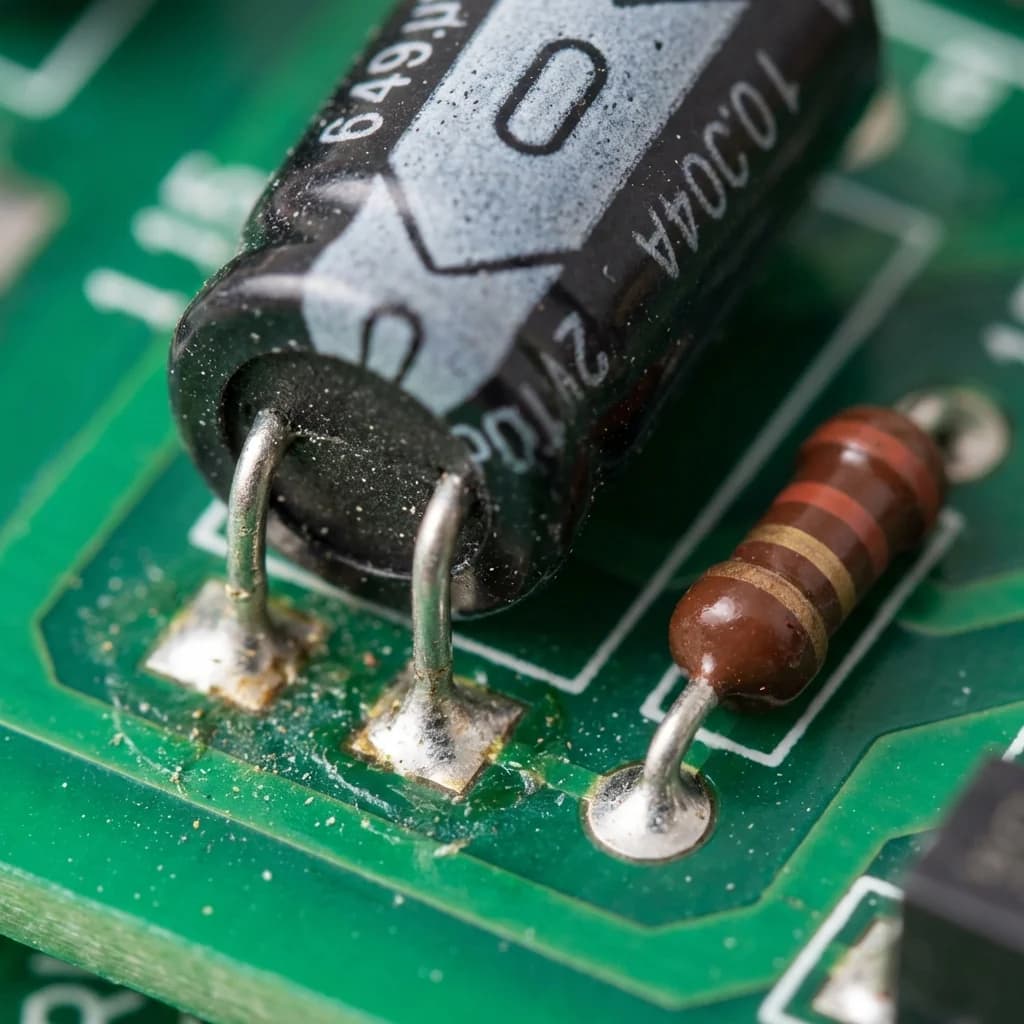
Older capacitors (especially mica, ceramic disc, and some tubular types) used colored bands or dots to indicate value, similar to resistor color coding.
| Color | Digit | Multiplier | Tolerance | Voltage (in some systems) |
|---|
| Black | 0 | ×1 | ±20% (M) | — |
| Brown | 1 | ×10 | ±1% (F) | 100V |
| Red | 2 | ×100 | ±2% (G) | 200V |
| Orange | 3 | ×1,000 | — | 300V |
| Yellow | 4 | ×10,000 | — | 400V |
| Green | 5 | ×100,000 | ±5% (J) | 500V |
| Blue | 6 | ×1,000,000 | — | 600V |
| Violet | 7 | — | — | 700V |
| Gray | 8 | ×0.01 | — | 800V |
| White | 9 | ×0.1 | ±10% (K) | 900V |
5-band system (most common for mica and older ceramic):
Band 1: First digit
Band 2: Second digit
Band 3: Multiplier
Band 4: Tolerance
Band 5: Voltage (if present)
Result is in picofarads (pF).
Example: Brown-Black-Orange-Green = 10 × 1,000 = 10,000 pF (10 nF) ±5%
Some silver mica capacitors use a 6-dot pattern. The first dot (often white or black) indicates the standard, and the remaining dots follow the color code for first digit, second digit, multiplier, tolerance, and characteristic.
Large electrolytic capacitors print specifications directly on the sleeve or can. Here's how to read every piece of information.
NICHICON LGU Series
6800µF  450V DC
105°C  10000h
Ripple: 8.58A (120Hz, 105°C)
⊖ ━━━━━━━━━━━━━━━━ ⊕
P/N: LGU2W682MELC
Decoding the label:
| Field | Meaning |
|---|
| NICHICON | Manufacturer |
| LGU Series | Product series (determines specs like ESR, life) |
| 6800µF | Capacitance: 6,800 microfarads |
| 450V DC | Maximum working voltage: 450 volts DC |
| 105°C | Maximum rated temperature |
| 10000h | Rated life at max temperature and voltage |
| 8.58A | Maximum ripple current at 120Hz, 105°C |
| ⊖ / ⊕ | Polarity indicators (negative stripe, positive marking) |
| P/N | Manufacturer part number |
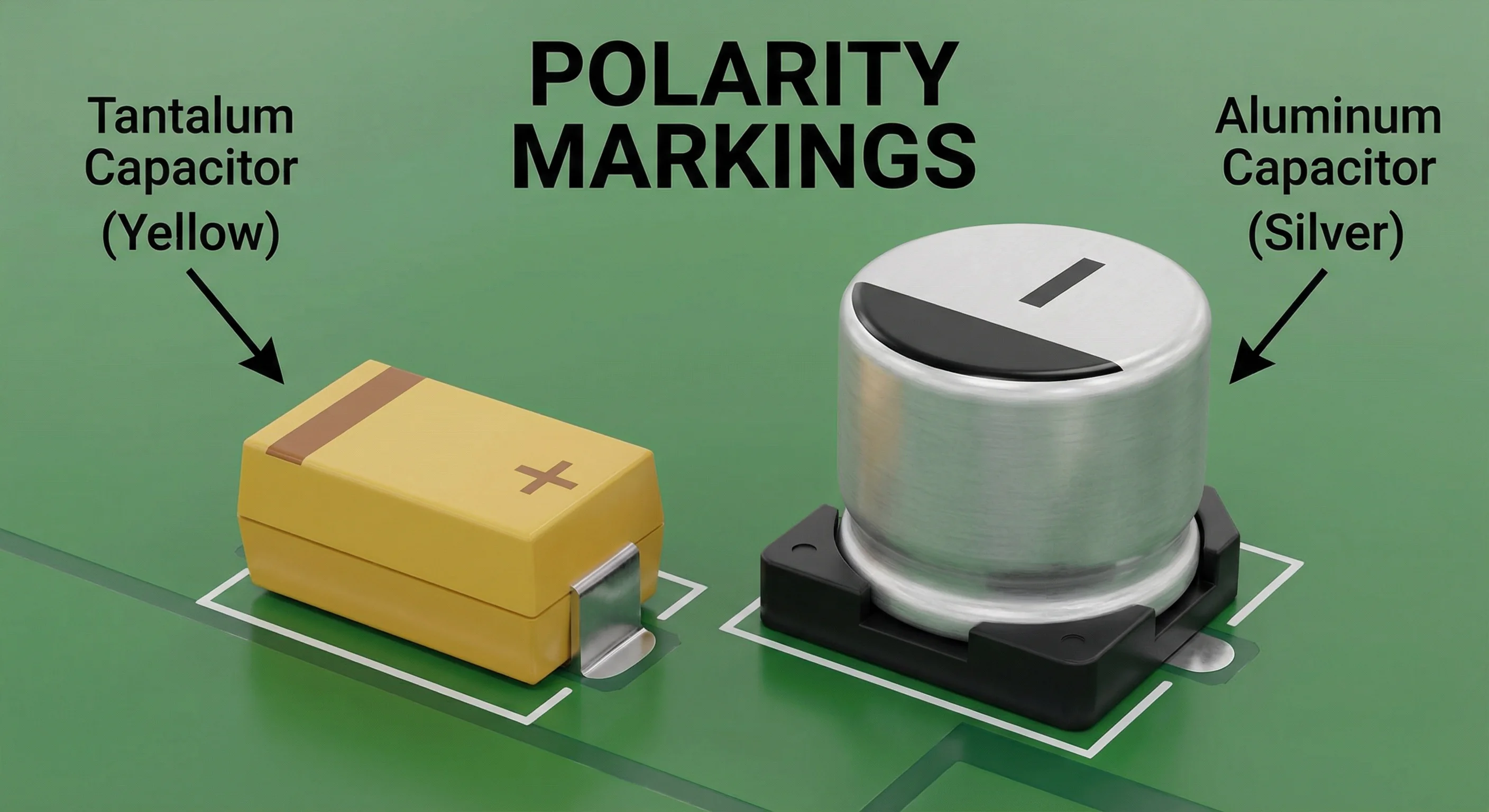
Electrolytic capacitors are polarized — reversing polarity causes failure. Markings differ by type:
Radial (vertical, leads from bottom):
- Negative (-) terminal: Marked with a stripe of minus signs (- - - -) on the sleeve
- Positive (+) terminal: Longer lead (on new parts)
Axial (horizontal, leads from each end):
- Positive (+) terminal: Often marked with a band or indent at one end
- Check manufacturer's convention — it varies
Screw terminal / Computer grade:
- Terminals are clearly marked + and - on the top plate
- Some use red (+) and black (-) insulators
SMD electrolytic:
- Positive (+) end: Marked with a bar or notch on the case top
- Opposite of through-hole convention (through-hole marks negative)
Most electrolytic capacitors include a date code indicating when they were manufactured:
| Format | Example | Meaning |
|---|
| YYMM | 2401 | January 2024 |
| YWWK | 4 12 K | 2024, week 12 |
| Year + Week | 23-48 | 2023, week 48 |
| Lot code | Varies | Manufacturer-specific encoding |
Date codes are important for determining shelf life and whether reforming is needed for stored capacitors.
Motor capacitors (start and run types) have their own labeling conventions.
CAPACITOR
CBB65  35µF ±5%
440 VAC  50/60Hz
S2 (P2)
| Field | Meaning |
|---|
| CBB65 | Construction type (metallized polypropylene, oval can) |
| 35µF | Capacitance |
| ±5% | Tolerance |
| 440 VAC | AC voltage rating |
| 50/60Hz | Frequency rating |
| S2 | Safety class (self-healing) |
DUAL RUN CAPACITOR
35 + 5 µF ±6%
440 VAC  50/60Hz
     C
    / \
HERM   FAN
| Terminal | Connection |
|---|
| C | Common (connects to both sections) |
| HERM | Compressor motor (35 µF section) |
| FAN | Fan motor (5 µF section) |
The larger value always goes to the compressor, the smaller to the fan.
MOTOR START CAPACITOR
108-130 µF
165 VAC
50/60Hz
Motor start capacitors often show a range (108-130 µF) rather than a single value, because they're used briefly and exact value is less critical than being within the specified range.
WIMA MKP10
0.47µF (474)  630V DC / 250V AC
±10%  85°C
| Field | Meaning |
|---|
| WIMA | Manufacturer |
| MKP10 | Series (Metallized Polypropylene) |
| 0.47µF (474) | Capacitance in both direct and coded format |
| 630V DC / 250V AC | Both DC and AC voltage ratings |
| ±10% | Tolerance |
| 85°C | Maximum operating temperature |
| Code | Dielectric | Full Name |
|---|
| MKP | Polypropylene | Metallized Polypropylene |
| MKT | Polyester | Metallized Polyester (Mylar) |
| MKS | Polyester | Metallized Polyester (stacked) |
| MKC | Polycarbonate | Metallized Polycarbonate |
| FKP | Polypropylene | Foil and Polypropylene |
| CBB | Polypropylene | Common Chinese standard code |
| CL | Polyester | Common Chinese standard code |
Many manufacturers encode specifications in their part numbers. Here are some common patterns.
LGU2W682MELC
│││││││││└└└── Package/terminal info
││││││││└───── Tolerance: M = ±20%
│││││└└└────── Capacitance: 682 = 6800µF
││││└────────── Voltage: 2W = 450V
│└└└──────────── Series: LGU
└──────────────── Manufacturer prefix
381LR682M450A052
│││ │││││ │││ └└└── Can size (diameter × height in mm)
│││ │││││ └└└────── Voltage: 450V
│││ ││││└────────── Tolerance: M = ±20%
│││ └└└└──────────── Capacitance: 682 = 6800µF
└└└────────────────── Series: 381LR
EEEFK1V101P
│││││││││ └── Package info
││││││└└└──── Capacitance: 101 = 100µF
│││││└─────── Voltage: 1V = 35V
││││└──────── Dielectric: FK = specific series
└└└└────────── Prefix: EEE = Aluminum Electrolytic
Confusion between picofarads, nanofarads, and microfarads is the most common source of errors. Use this table:
| Picofarads (pF) | Nanofarads (nF) | Microfarads (µF) | 3-Digit Code |
|---|
| 1 pF | 0.001 nF | 0.000001 µF | 010 |
| 10 pF | 0.01 nF | 0.00001 µF | 100 |
| 100 pF | 0.1 nF | 0.0001 µF | 101 |
| 1,000 pF | 1 nF | 0.001 µF | 102 |
| 10,000 pF | 10 nF | 0.01 µF | 103 |
| 100,000 pF | 100 nF | 0.1 µF | 104 |
| 1,000,000 pF | 1,000 nF | 1 µF | 105 |
| 10,000,000 pF | 10,000 nF | 10 µF | 106 |
Conversion shortcuts:
- pF to nF: divide by 1,000
- nF to µF: divide by 1,000
- pF to µF: divide by 1,000,000
When capacitor markings are illegible:
- Measure with a capacitance meter — Gives you the actual value regardless of markings
- Check the schematic — The circuit design documents specify the value
- Look for PCB silkscreen — Often printed near the component location (C1, C2, etc.) with value
- Photograph under angled light — Raised or embossed markings may be visible at certain angles
- Check the BOM — Bill of materials lists every component and its value
- Match physical size — If you know the type and can measure the package, you can narrow down possibilities
This is a common source of confusion:
| Marking | Actual Meaning |
|---|
| µF | Microfarad (standard modern notation) |
| uF | Microfarad (ASCII substitute for µ) |
| MFD | Microfarad (older American notation — NOT millifarad) |
| mF | Millifarad on datasheets, but often means microfarad on old components |
| MFCD | Microfarad (older notation) |
| mmF | Micro-microfarad = picofarad (obsolete term) |
| pF | Picofarad |
| nF | Nanofarad |
Critical: On vintage American capacitors, "MFD" means microfarad, not millifarad. A label reading "100 MFD" means 100 µF, not 100 mF (which would be 100,000 µF).
104 is a 3-digit capacitance code meaning 10 × 10⁴ picofarads = 100,000 pF = 100 nF = 0.1 µF. The first two digits (10) are the significant figures, and the third digit (4) is the number of zeros to add.
They mean the same thing — microfarads. MFD is an older American abbreviation that was commonly used before the Greek letter µ became standard on component markings. A capacitor marked "50 MFD" is 50 µF.
Use a digital multimeter with a capacitance function. Set it to the appropriate range, discharge the capacitor fully, and measure. The reading gives you the actual capacitance. For the voltage rating, you'll need to reference the circuit design or replace with a conservatively high voltage rating.
K is a tolerance code meaning ±10%. For example, "104K" means 0.1 µF with ±10% tolerance. Other common tolerance letters: J = ±5%, M = ±20%.
Read the bands like a resistor: first band = first digit, second band = second digit, third band = multiplier. The result is in picofarads. Fourth band (if present) = tolerance, fifth band = voltage or temperature rating.
CBB is a Chinese standard designation for metallized polypropylene film capacitors. CBB60 indicates a cylindrical plastic-case motor capacitor. CBB65 indicates an oval or round aluminum-case motor capacitor designed for higher-temperature environments (typically HVAC outdoor units).
- The 3-digit code is king — Most small capacitors use it: two significant digits plus a multiplier, result in picofarads
- R marks the decimal — In codes like 4R7, the R is a decimal point (4.7 pF)
- Tolerance follows the value — J = ±5%, K = ±10%, M = ±20%
- Electrolytic labels are direct — They print µF, voltage, temperature, and polarity in plain text
- MFD = µF — On vintage capacitors, MFD is microfarads, not millifarads
- When in doubt, measure — A $20 multimeter with capacitance mode solves most identification problems
- Polarity matters — Electrolytic: negative stripe on the sleeve. SMD electrolytic: positive bar on top
- Capacitor Types Guide — Complete comparison of all capacitor types with specs and selection tips to complement what you decode from markings
- Capacitor Value Calculator — Convert between pF, nF, and µF units and calculate series/parallel combinations
- Capacitor Glossary — 50+ capacitor terms defined, including marking abbreviations and industry terminology
Can't decode a capacitor marking? Send us a clear photo of the label and we'll identify it for you. Our team has been reading capacitor codes for over 40 years — we've seen every marking system there is.