How to Test a Capacitor with a Multimeter: Step-by-Step Guide
Last Updated: January 2026 | Reading Time: 12 minutes
A failed capacitor is one of the most common causes of electronic equipment failure. Fortunately, testing capacitors is straightforward with basic tools. Whether you're diagnosing a dead power supply, a malfunctioning air conditioner, or vintage audio equipment, knowing how to test capacitors saves time and money.
This guide covers multiple testing methods using a standard multimeter, from quick checks to more thorough diagnostics.
Capacitors store electrical energy and can deliver dangerous or lethal shocks.
- Disconnect power — Unplug equipment or turn off breaker
- Discharge the capacitor — Large capacitors can hold charge for hours or days
- Verify zero voltage — Use your multimeter to confirm
- Avoid touching terminals — Even "discharged" capacitors can retain some energy
- Work in a dry area — Moisture increases shock risk
For small capacitors (under 50V, under 1000µF):
- Touch a screwdriver across the terminals (may produce small spark)
For larger capacitors:
Use a discharge resistor to prevent damage and reduce spark:
- Select a resistor: 1,000-20,000 ohms, rated for at least 5 watts
- Connect resistor across capacitor terminals
- Wait 5-30 seconds (longer for larger capacitors)
- Verify discharge with multimeter
Discharge formula: Time (seconds) = 5 × R × C
- R = resistance in megohms
- C = capacitance in microfarads
Example: 10,000µF capacitor with 1,000 ohm resistor
- Time = 5 × 0.001 × 10,000 = 50 seconds to fully discharge
Most modern digital multimeters include a capacitance measurement function. This is the most accurate method.
- Digital multimeter with capacitance mode (display shows "µF" or "nF")
- Alligator clip leads (optional but helpful)
Step 1: Prepare the capacitor
- Remove from circuit (recommended for accuracy)
- Discharge completely
- Clean terminals if corroded
Step 2: Set up the multimeter
- Turn dial to capacitance mode (often marked with capacitor symbol or "µF")
- Select appropriate range if not auto-ranging
- Connect leads to meter inputs (typically the same as resistance)
Step 3: Connect and measure
- Touch red probe to positive terminal (if polarized)
- Touch black probe to negative terminal
- Wait for reading to stabilize (may take several seconds)
Step 4: Interpret results
| Reading | Interpretation |
|---|
| Within ±20% of rated value | Good (acceptable for electrolytics) |
| Within ±5% of rated value | Good (acceptable for film/ceramic) |
| Significantly low | Degraded or failed |
| Zero or OL (overload) | Open circuit — failed |
| Very high (beyond tolerance) | Unusual — possible meter error |
- May not detect high ESR (internal resistance)
- Some meters inaccurate on very small (<10pF) or very large (>10,000µF) capacitors
- Cannot test capacitor's voltage rating
- Cannot detect intermittent failures
When your multimeter lacks capacitance mode, resistance testing provides useful diagnostic information.
A capacitor in good condition will:
- Initially show very low resistance
- Resistance increases as capacitor charges from meter battery
- Eventually show open circuit (infinity/OL)
This behavior indicates the capacitor is charging—a healthy sign.
Step 1: Prepare the capacitor
- Remove from circuit
- Discharge completely
- Clean terminals
Step 2: Set up the multimeter
- Select resistance mode (ohms)
- Choose high range (megohms) for small capacitors
- Choose low range (kilohms) for large capacitors
Step 3: Connect and observe
- Touch probes to capacitor terminals
- Watch the display immediately
Step 4: Interpret the behavior
| Behavior | Interpretation |
|---|
| Resistance starts low, steadily increases to infinity | Good capacitor |
| Resistance stays at zero | Shorted — definitely failed |
| Resistance stays at infinity immediately | Open circuit — failed |
| Resistance stays at fixed mid-range value | Leaky — failed |
Repeat the test:
- Discharge capacitor between tests
- Swap probe polarity and repeat
- Behavior should be similar in both directions
For very small capacitors:
- Charging happens almost instantly
- May see only a brief "blip" before infinity
- This is normal for low capacitance values
For very large capacitors:
- Charging takes longer
- Watch for steady increase over several seconds
- May never reach infinity on meter's timeout
This test verifies the capacitor can hold a charge—its fundamental purpose.
- Multimeter with DC voltage mode
- Safe DC power source (lower than capacitor's voltage rating)
- Resistor for discharge (1K-10K ohms)
Step 1: Charge the capacitor
- Use a DC power source rated well below the capacitor's voltage
- Apply voltage for 5-10 seconds
- Disconnect power source
Step 2: Measure retained voltage
- Immediately measure voltage across terminals
- Note the initial reading
Step 3: Monitor over time
- Check voltage again after 1 minute
- Check again after 5 minutes
Step 4: Interpret results
| Result | Interpretation |
|---|
| Voltage present immediately after charging | Basic function confirmed |
| Voltage holds steady | Good capacitor |
| Voltage drops rapidly | Leaky — failing or failed |
| No voltage retained | Shorted or severely failed |
Good electrolytic capacitors should retain at least 80-90% of charge after a few minutes. Some voltage loss is normal due to internal leakage, especially for electrolytic types.
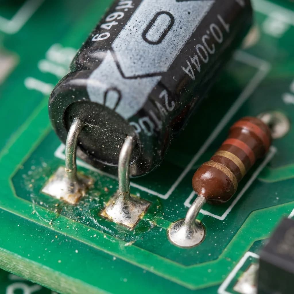
Before electrical testing, visual inspection often reveals obvious failures.
Electrolytic Capacitors:
| Sign | Meaning |
|---|
| Bulging top | Internal pressure from failure — replace immediately |
| Leaked electrolyte | Seal failure — replace immediately |
| Discolored leads | Overheating history — suspect |
| Crooked or tilted | Heat damage — replace |
| Cracked case | Physical damage — replace |
| Rust or corrosion | Age/environmental damage — test carefully |
Film and Ceramic Capacitors:
| Sign | Meaning |
|---|
| Cracked body | Likely failed — test |
| Burn marks | Overheated — likely failed |
| Loose leads | Mechanical damage — test |
| Discoloration | Overheating — test |
Failed electrolytic capacitors often have a distinctive odor—described as fishy, chemical, or like burnt electronics. If you smell this near capacitors, they're likely failed or failing.
Sometimes removing capacitors isn't practical. In-circuit testing has limitations but provides useful information.
- Other components affect readings
- Parallel capacitors combine values
- Resistors in parallel mask true capacitance
- Voltage present on powered circuits
- Obvious failures (shorted capacitors show zero ohms)
- ESR testing with specialized meters
- Visual inspection without removal
- Voltage testing with power applied (carefully)
- Power off and discharge
- Test with resistance mode first
- Look for obvious shorts or opens
- Remove suspect capacitors for accurate testing
ESR (Equivalent Series Resistance) testing is the gold standard for evaluating electrolytic capacitor health.
Standard capacitance tests may show acceptable values on capacitors that have failed in application. ESR testing reveals internal degradation invisible to capacitance testing.
Dedicated ESR meters:
- Test at frequency where ESR is measurable (typically 100kHz)
- Can test in-circuit (in many cases)
- Provide numerical ESR reading
- Some include capacitance measurement
ESR values vary by capacitor size and type. General guidelines:
| Capacitance | Typical Good ESR |
|---|
| 1-10 µF | 2-10 ohms |
| 10-100 µF | 0.5-2 ohms |
| 100-1000 µF | 0.1-0.5 ohms |
| 1000+ µF | 0.01-0.1 ohms |
Higher than expected ESR indicates:
- Electrolyte drying out
- Internal connection degradation
- End of useful life
Most common type to fail. Test with:
- Capacitance mode (within ±20% of rated value)
- Resistance mode (charging behavior)
- Visual inspection (bulging, leaking)
- ESR testing if available
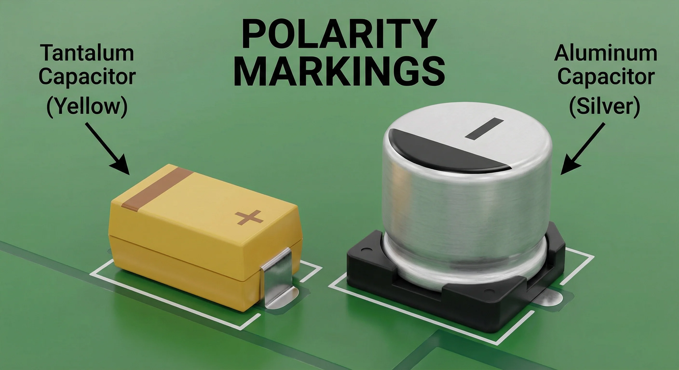
Polarity matters: Connect positive to positive, negative to negative
Rarely fail but when they do:
- Capacitance mode (within ±5-10% of rated value)
- Resistance mode (should show infinity quickly)
- Visual inspection (cracking, burn marks)
No polarity concerns: Can connect either way
May fail open or short:
- Capacitance mode (tight tolerance expected)
- Resistance mode (should show infinity instantly)
- Visual inspection (cracks)
Note: Very small ceramic capacitors may be difficult to measure accurately with standard meters.
Usually electrolytic, test with:
- Capacitance mode (within ±10-15% of rated value)
- Resistance mode (charging behavior)
- Visual inspection
Oil-filled film type, test with:
- Capacitance mode (within ±5% of rated value)
- Resistance mode (should show infinity)
- Visual inspection (bulging, oil leakage)
Stored charge can damage your meter or give false readings. Always discharge first.
Parallel components skew readings. Remove capacitors for accurate testing when possible.
If a capacitor looks failed (bulging, leaking), it is failed. No testing needed.
Ensure your meter is set correctly:
- Capacitance mode for capacitance
- DC voltage mode for voltage testing
- Correct range selected
Large capacitors hold charge. Wait and discharge properly before testing.
A capacitor can show correct capacitance but have unacceptably high ESR. Capacitance testing alone doesn't catch all failure modes.
- Visibly bulging or leaking capacitors
- Capacitors in failed equipment that match failure symptoms
- Capacitors over 15-20 years old in critical applications
- Capacitors near obvious burn marks or heat damage
- Intermittent problems with unknown cause
- Equipment that partially works
- When original problem might not be capacitor-related
- Salvaged or used capacitors before reuse
You can perform basic resistance testing in-circuit, but results are affected by parallel components. For accurate capacitance readings, removal is recommended.
The capacitor likely has internal shorts or extremely high leakage. This indicates failure.
Small increases (up to +80% for standard electrolytics) may be within tolerance. Readings far above rated value suggest meter error or a problem with the capacitor.
Most standard multimeters cannot accurately measure picofarad capacitors. You need a meter specifically designed for small capacitance ranges or an LCR meter.
For critical applications, testing new capacitors verifies they weren't damaged in shipping and confirms correct values before installation.
The capacitor may have intermittent failures under load or at temperature. It could also pass basic tests but have ESR issues. Or the problem might not be capacitor-related.
| Test | Good Result | Failed Result |
|---|
| Visual | No bulging, leaking, damage | Any visible damage |
| Capacitance | Within tolerance | Zero, OL, or far out of spec |
| Resistance | Charges up to infinity | Stays at zero, stays at infinity, or stays at fixed value |
| Voltage Retention | Holds charge | Rapid discharge or no charge |
| ESR | Within expected range | Elevated ESR |
- Safety first — Always discharge before testing
- Visual inspection often tells you everything — Bulging = failed
- Capacitance mode is most accurate — Use it if available
- Resistance mode shows charging behavior — Low to high indicates health
- ESR testing catches failures capacitance testing misses — Consider for critical work
- Remove capacitors for accurate testing — In-circuit has limitations
- When in doubt, replace — Capacitors are usually inexpensive compared to troubleshooting time
Found a failed capacitor and need a replacement? We stock over 10,000 capacitor SKUs, from common values to hard-to-find obsolete types. Let us know what you need—part number, capacitance, voltage, and physical size—and we'll find the right replacement for your application.