Capacitor Failure Modes: Complete Guide to Why Capacitors Fail and How to Prevent It
Last Updated: February 2026 | Reading Time: 14 minutes
Capacitors are the most failure-prone passive component in electronic systems. They fail more often than resistors, inductors, or connectors. And unlike resistors — which typically fail open and stop a circuit — capacitor failures can be dramatic: short circuits, electrolyte leaks, thermal runaway, or even small explosions. Every engineer, maintenance technician, and reliability professional should understand how and why capacitors fail.
The failure mechanisms differ dramatically by capacitor type. An electrolytic capacitor fails for fundamentally different reasons than a ceramic capacitor, and a tantalum capacitor has failure modes that neither of those share. Understanding these mechanisms lets you prevent failures through proper selection, derating, and maintenance — rather than discovering them through unplanned downtime and root-cause analysis.
This guide covers the six primary capacitor failure mechanisms, how to detect them, and specific prevention strategies for each.
Mechanism: Aluminum electrolytic capacitors use a liquid or gel electrolyte to form the actual cathode contact with the dielectric oxide layer. This electrolyte slowly evaporates through the rubber end seal over the entire life of the capacitor. As electrolyte volume decreases, the effective plate area shrinks, capacitance drops, and ESR rises.
This is not a defect — it is a fundamental characteristic of the technology. Every aluminum electrolytic capacitor will eventually dry out. The only question is when.
Symptoms:
- Gradual capacitance decrease (typically 10-40% loss before functional failure)
- ESR increase (often the first parameter to go out of specification)
- Increased AC ripple voltage across the capacitor
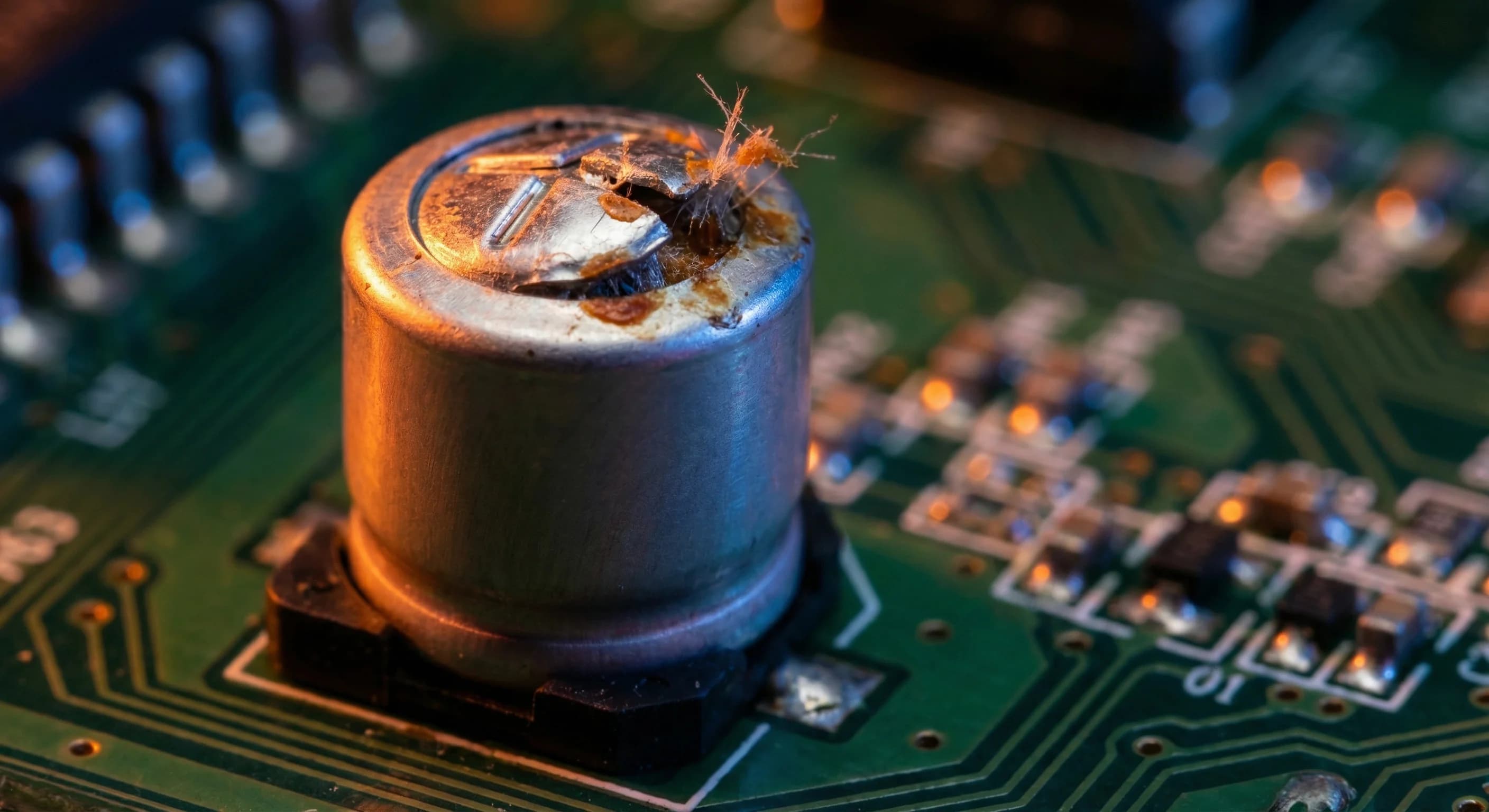
- Visible bulging of the capacitor's pressure relief vent
- Brown or crusty residue around the base (leaked electrolyte)
Rate of Degradation:
The Arrhenius equation governs electrolyte evaporation:
Life = L_base * 2^((T_max - T_actual) / 10)

Example: A capacitor rated 5,000 hours at 105°C
  At 85°C: 5,000 * 2^((105-85)/10) = 5,000 * 4 = 20,000 hours
  At 65°C: 5,000 * 2^((105-65)/10) = 5,000 * 16 = 80,000 hours (~9 years)
  At 45°C: 5,000 * 2^((105-45)/10) = 5,000 * 64 = 320,000 hours (~36 years)
Temperature is the dominant factor. A 20°C reduction in operating temperature quadruples the expected life.
Testing Methods:
- Capacitance measurement with an LCR meter or capacitance meter
- ESR measurement with a dedicated ESR meter (more sensitive than capacitance for early detection)
- Visual inspection for bulging, leaking, or discoloration
- DC bus ripple voltage measurement in power supplies and drives
Prevention:
- Choose 105°C-rated capacitors over 85°C wherever possible — see our 85°C vs 105°C comparison
- Derate temperature: keep capacitors at least 20°C below their maximum rated temperature
- Ensure adequate airflow around electrolytic capacitors
- Position electrolytics away from heat-generating components (power transistors, resistors, transformers)
- For long-life applications, specify capacitors with rated life of 10,000+ hours at 105°C
Mechanism: Every capacitor dielectric has a maximum electric field strength it can withstand. Exceeding this field strength — whether through overvoltage, voltage transients, or dielectric degradation — causes the insulating material to break down and conduct. In most capacitor types, this creates a permanent short circuit.
Affected types: All capacitor types, but the consequences vary:
| Capacitor Type | Dielectric | Breakdown Behavior |
|---|
| Ceramic (MLCC) | Ceramic (BaTiO3) | Permanent short circuit — can catch fire |
| Film | Polypropylene, polyester | Self-healing (metallized) or permanent short (foil) |
| Electrolytic | Aluminum oxide (Al2O3) | Short circuit with possible thermal runaway |
| Tantalum | Tantalum pentoxide (Ta2O5) | Short circuit with violent thermal runaway |
| Mica | Mica | Permanent short — rare due to high breakdown voltage |
Symptoms:
- Immediate: blown fuse, tripped breaker, smoke, or visible damage
- Intermittent: arcing sounds, erratic behavior at high operating voltages
- In film capacitors: gradual capacitance loss as self-healing events consume metallization
Testing Methods:
- Insulation resistance measurement (megohmmeter) — should be > 100 MΩ for most types
- Capacitance measurement — sudden drops indicate partial breakdown
- Dissipation factor measurement — increases after partial breakdown events
Prevention:
- Voltage derating: operate capacitors at no more than 70-80% of their rated voltage. See our derating guide for detailed recommendations by type.
- Account for voltage transients — the peak voltage, not just the RMS or DC level, determines stress
- For AC applications, verify the capacitor is rated for AC voltage (not just DC)
- Avoid voltage reversal on polarized capacitors (electrolytic, tantalum) — even brief reversals can initiate breakdown
- Select capacitors with adequate voltage margin for the application's worst-case transient conditions
Mechanism: ESR (Equivalent Series Resistance) represents all resistive losses inside a capacitor — lead resistance, plate resistance, contact resistance, and electrolyte resistance. In electrolytic capacitors, ESR rise is primarily driven by electrolyte degradation. In other types, it can result from internal connection degradation, corrosion, or moisture ingress.
Why ESR matters more than capacitance: In many power applications, ESR rise causes functional failure before capacitance drops to a problematic level. A capacitor with adequate capacitance but high ESR generates excessive heat under ripple current, creates voltage drops at the output, and provides poor high-frequency filtering.
For example, in a switching power supply, a doubling of ESR in the output filter capacitor can increase output ripple voltage by 100% — potentially exceeding specification limits and causing downstream equipment to malfunction — even while the capacitance value remains within tolerance.
Symptoms:
- Increased output ripple in power supplies
- Overheating of the capacitor under load
- Reduced efficiency in power converters
- Audible noise from power supplies (magnetostriction from ripple currents)
Testing Methods:
- Dedicated ESR meter (measures at 100 kHz, the most relevant frequency for switching applications)
- LCR meter with ESR/dissipation factor capability
- In-circuit AC voltage measurement across the capacitor under load
- Thermal imaging to identify hot capacitors
For a thorough explanation of ESR and how to measure it, see our ESR guide.
Prevention:
- Select low-ESR capacitors for switching power supply applications
- Derate ripple current to 70-80% of the capacitor's rated maximum
- Ensure thermal management keeps capacitor temperature well below maximum rating
- In high-ripple applications, parallel multiple capacitors to share ripple current
Mechanism: Capacitance changes over time due to several mechanisms depending on the dielectric type:
| Capacitor Type | Aging Mechanism | Typical Drift |
|---|
| Class II/III Ceramic (X7R, X5R, Y5V) | Crystal structure relaxation in BaTiO3 | -1% to -5% per decade (log time) |
| Class I Ceramic (C0G/NP0) | Minimal — stable crystal structure | < 0.1% over life |
| Aluminum Electrolytic | Electrolyte evaporation | -10% to -40% over useful life |
| Film | Very stable | < 1% over 20+ years |
| Tantalum | Oxide growth | +2% to +10% over life (capacitance increases) |
The ceramic aging trap: Class II and III ceramics (X7R, X5R, Y5V) lose capacitance logarithmically with time after their last exposure to temperatures above the Curie point. This is a reversable, predictable phenomenon. A Y5V capacitor can lose 20-60% of its capacitance over time — a fact often overlooked in designs that select based on fresh-from-factory measurements.
Additionally, Class II ceramics exhibit DC bias derating — capacitance drops significantly when DC voltage is applied. A 10 uF X5R capacitor rated at 16V may provide only 4-5 uF at 12V applied DC. This is separate from aging and combines with it to reduce effective capacitance in service.
Symptoms:
- Timing circuits drift out of specification
- Filter corner frequencies shift
- Resonant circuits detune
- Power supply ripple increases gradually
Testing Methods:
- Periodic capacitance measurement with an LCR meter
- Compare measured values to the capacitor's datasheet aging curves
- For ceramics: measure at the exact conditions specified (voltage, frequency, temperature)
Prevention:
- Use C0G/NP0 ceramics for timing and precision circuits — they do not age
- For Class II ceramics, add margin for aging and DC bias in your design (often 30-50% additional capacitance)
- Choose film capacitors for applications requiring long-term stability
- Specify end-of-life capacitance requirements, not just initial values
Mechanism: Tantalum capacitors and multilayer ceramic capacitors (MLCCs) have distinct short-circuit failure modes that can be catastrophic.
Tantalum: The tantalum pentoxide dielectric is extremely thin (nanometers) to achieve high capacitance density. Any defect in the dielectric — a microscopic void, contamination, or crystalline flaw — can initiate a conductive path. Under voltage stress, this path grows through a mechanism similar to electromigration, eventually creating a full short circuit. Because tantalum has a high heat of combustion, the resulting short circuit can cause the capacitor to ignite — a well-documented failure mode that has caused PCB fires and equipment damage.
MLCC: Multilayer ceramic capacitors can fail short due to cracks that bridge internal electrode layers. These cracks create a low-resistance path that carries increasing current, generating heat, and eventually creating a permanent short. The failure can be immediate (from a manufacturing defect) or delayed (from mechanical stress cracks that propagate over time).
Symptoms:
- Tantalum: sudden short circuit, possible smoke or flame, burnt component
- MLCC: intermittent short circuits that may self-heal temporarily, eventual permanent short
- In both: blown fuses, blown traces, damage to surrounding components
Testing Methods:
- Insulation resistance measurement before installation
- X-ray inspection for internal cracks in MLCCs (production environments)
- Incoming inspection with voltage screening for tantalum capacitors
- Thermal shock testing during qualification to reveal latent cracks
Prevention:
- Tantalum: derate to 50% of rated voltage (industry standard for reliability). Use polymer tantalum types where possible — they fail open instead of short.
- MLCC: avoid mechanical stress during soldering and assembly. Use flex-resistant terminations for large case sizes (1210, 1812, 2220). Avoid placing large MLCCs near PCB mounting holes or flex points.
- Both: thorough incoming inspection and qualification testing
- Consider film capacitors as alternatives in applications where short-circuit failure is unacceptable
Mechanism: Capacitors are physical objects subject to mechanical stress from thermal cycling, vibration, board flexure, and handling. Mechanical failures include:
- Ceramic capacitor cracking — MLCCs are brittle and crack from board flexure, thermal shock, or excessive soldering force. Cracks can bridge electrodes creating shorts, or sever connections creating opens.
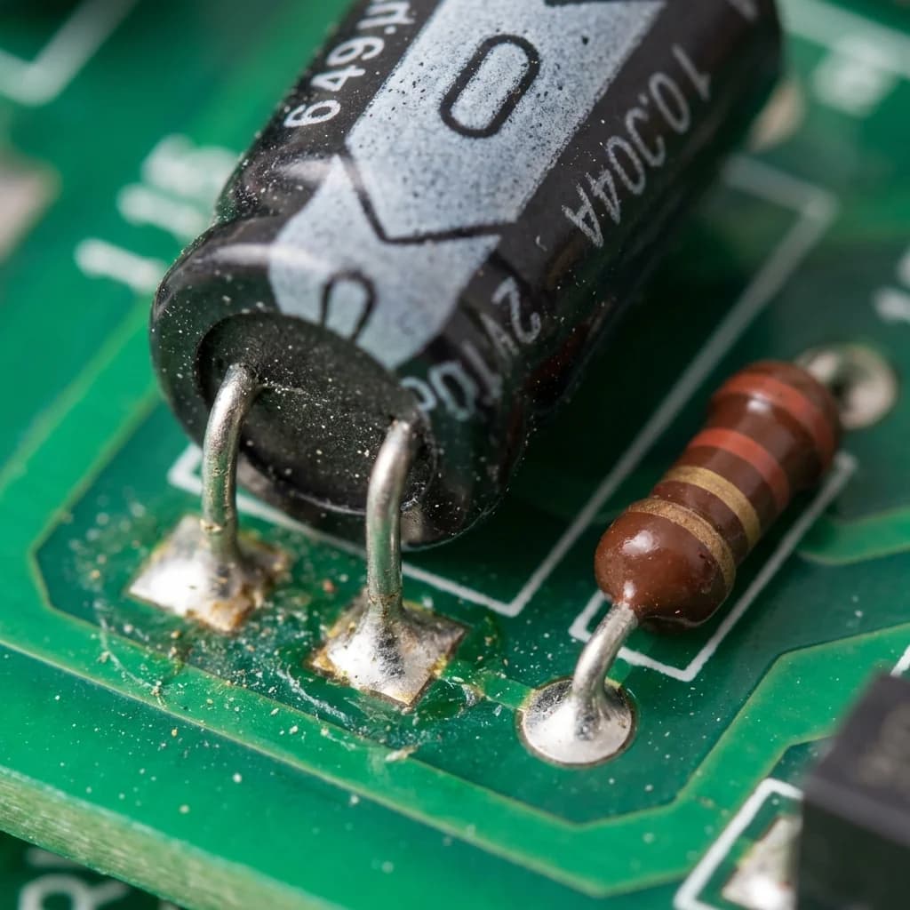
- Lead wire fatigue — Through-hole capacitors in high-vibration environments develop fatigue cracks at the lead-to-body junction. This is especially common in radial electrolytic capacitors that are top-heavy.
- Solder joint failure — Thermal cycling causes solder joints to fatigue and crack, particularly for large SMD components. This is exacerbated by CTE (coefficient of thermal expansion) mismatch between the ceramic body and the PCB.
- Terminal corrosion — In humid or corrosive environments, capacitor terminals can corrode, increasing contact resistance or creating open circuits.
Symptoms:
- Intermittent open circuits (especially with cracked solder joints or leads)
- Sudden shorts in ceramic capacitors from flex cracks
- Audible rattling in severely damaged components
- Green or white corrosion on terminals
- Visible cracks in ceramic capacitor bodies (sometimes require magnification)
Testing Methods:
- Visual inspection under magnification (10-30x)
- Capacitance measurement with gentle flexing of the PCB to detect intermittent opens
- Thermal cycling testing during qualification
- Vibration testing per application requirements
- Cross-section analysis for failure investigation
Prevention:
- Use strain-relief mounting for through-hole capacitors in vibration environments (adhesive bonding to PCB, mechanical brackets)
- Follow IPC soldering guidelines for reflow profiles — avoid thermal shock
- Route board to minimize flexure near large ceramic capacitors
- Use smaller MLCC case sizes where possible (0402, 0603) — they are more resistant to flex cracking than large packages
- For high-vibration applications, consider leaded MLCCs or film capacitors instead of standard SMD ceramics
- Apply conformal coating in humid or corrosive environments
| Failure Mode | Primary Capacitor Types | Failure Speed | Detectability | Severity |
|---|
| Electrolyte dry-out | Aluminum electrolytic | Gradual (years) | Moderate — ESR testing | Medium |
| Dielectric breakdown | All types | Sudden | Low before failure | High |
| ESR rise | Electrolytic, tantalum | Gradual (months-years) | High — ESR meter | Medium |
| Capacitance drift | Ceramic (Class II/III), electrolytic | Gradual (years) | High — capacitance meter | Low-Medium |
| Short circuit | Tantalum, MLCC | Sudden | Low before failure | Very High |
| Mechanical failure | Ceramic (MLCC), through-hole | Variable | Moderate — visual/electrical | Medium-High |
The single most important factor. Higher operating temperatures accelerate every degradation mechanism. For electrolytic capacitors, life halves for every 10°C above the rated base temperature. For all types, elevated temperature increases chemical reaction rates, accelerates diffusion processes, and increases mechanical stress from thermal expansion.
Moisture penetrates through packaging materials and end seals, increasing leakage current and potentially causing corrosion of internal elements. This is particularly problematic for electrolytic capacitors in outdoor or non-climate-controlled environments. Conformal coating and hermetic packaging mitigate this factor.
Mechanical vibration causes fatigue in solder joints and lead wires, and can initiate or propagate cracks in ceramic capacitors. Industrial environments with motors, compressors, or heavy machinery generate vibration levels that significantly reduce capacitor life without proper mounting.
Operating capacitors near their rated voltage accelerates dielectric aging and increases the probability of breakdown during transient events. This is why voltage derating is the single most effective reliability improvement technique. For detailed derating guidelines by capacitor type, see our capacitor derating guide.
Specap has supplied capacitors to industrial, military, and commercial customers since 1984. We've seen every failure mode described in this guide — and helped thousands of customers select capacitors that avoid them. Whether you need high-reliability electrolytic capacitors rated for 10,000+ hours, automotive-grade MLCCs with flex-resistant terminations, or derating advice for a new design, our technical team can help.
Contact us for capacitor selection assistance, cross-references, or help diagnosing a capacitor failure in your equipment.